P-11/P-40 and P-32/P-3AT Disassembly

Back to Kel-Tec stuff

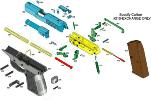
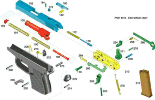
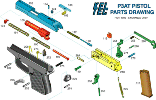
All part number references match these numbers:

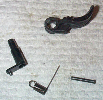
P-11 Parts
click to enlarge

P-32 Parts
click to enlarge

P-3AT Parts
click to enlarge


Everything for the P-11 is the same for the P-40, and with the execption of the extrator and lack of a slide stop the P-3AT is the same as the P-32 (differences are noted).

First lock the slide back, for both the P-11 and the P-32 you can lock the slide back by inserting an empty mag and pulling the slide back. Then release and remove the mag. For the P-3AT (and the P-32 if you wish) you can just push the slide back just a little to release the pressure on the pin, and pull it out.

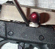
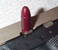
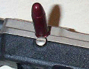
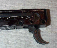
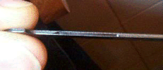
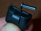
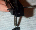
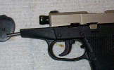
Now you can use a screwdriver, empty case, or snap cap (of the caliber of the gun) to pull out the assembly pin (Part 110). For the reason I use a screwdriver to push the spring down before pulling the assembly pin out on the P-11 and why my P-32 has a slot in the assembly pin it look here)

click to enlarge

click to enlarge

click to enlarge


Once the pin is out you can now pull back on the slide and slowly let it slide forward and keep sliding it off the frame (do not just pull it back and let it go!! it will fly off the frame and keep right on going).

For the P-3AT simply turning the grip and frame upside down after removing the slide will likely make the ejector (part 115) fall out. For the P-32 and the P-3AT the recoil spring catch (part 194) may fall out after you remove the recoil springs so it is best to remove these parts and set them asside so you don't loose them. Look here for for a method of attaching them so they don't fall out. (Also a dab of grease will help to hold them in and keep them from just falling out)

If you are just field stripping the gun, stop here. Skip down to here to see reassembly.

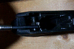
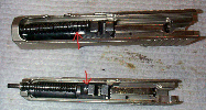
To remove the tension on the hammer spring you will have to "un hook" the lower spring anchoring point. You do this by inserting a flat blade screwdriver from the top of the gun through the mag well and into the Hammer Spring Catch (Part 279). Then, while holding the gun upside down, push the catch upward to get it out of it's groove and then forward slightly twisting it so it will fit through the mag well. (P-11 on the top row of pics and P-32 on the bottom)

click to enlarge

click to enlarge

click to enlarge

click to enlarge

click to enlarge

click to enlarge

click to enlarge


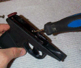
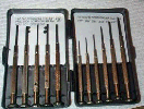
Now you will need something with a hole in it. I use a 2X4 with a 3/8" hole drilled in it. Rest the pistol so that one of the frame pins (Part 202) is over the hole in the 2X4 and tap it out using something flat and round. I use this small screw driver/Hex driver set I got at the dollar store. It has a hex driver that is just a bit smaller than the pins and works well to press them out. You can also use an appropriate sized blunt punch. When pushing out frame pins note which side you pushed them out from.

click to enlarge

click to enlarge


Press them out from the end of the pin that has the slight dip in the middle, if you look closely at the two ends of the pins you will see that there is a slight difference (although it realy does not matter it can be done from either side). You may be able to just press on them but more than likely will need to tap them out with a small hammer. Be careful not to miss or scratch up the under side of your KT.

This side

Not this side


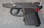
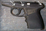
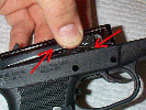
On the P-11 you will have to remove 3 pins, on the P-32 and P-3AT only remove the 2 plastic ones (White arrows), leave in the one metal one (red arrow) it is for the hammer block, which does not need to be removed for pulling the frame (it realy only has to be removed for a hammer block problem, rare, or swaping grips).

click to enlarge

click to enlarge


click to enlarge
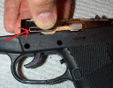
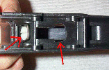
If you have a trigger shoe installed and have not modified the grip, you will have to remove the trigger shoe to get the frame out of the grip. I installed the trigger shoe on my P-11 with Ultra Black RTV silicone from the parts store (on the trigger, inside of the shoe and on the locking Hex screw threads), so mine is semi permanent (I have since permanently attached it with JB Weld). I enlarged the window that the trigger travels through in the grip (red arrow) so that I could remove the frame from the grip without removing the trigger shoe. You can also see the white head of the nylon screw (other red arrow) that is my trigger stop (for more info on the trigger stop look here). For more on a trigger shoe for the p-32 look here


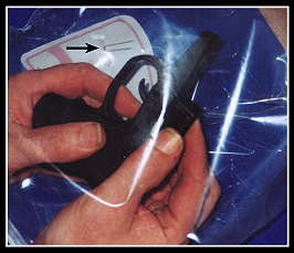
Now that you have all the pins out (2 for the P-32 and 3 for the P-11) and the trigger shoe off (or have a modified grip with a wide spot for the trigger shoe to go through), you can pull the frame up and out of the Polymer grip. But as you pull it out make sure that you do not loose the slide stop spring (Part 284, red arrow). It will fly out if you don't hold your finger over it when pulling the frame out of the grip. Also make sure you keep your fingers on the other side as well to keep the Trigger Spring (Part 256, red arrow) and Trigger Bar (Part 260, red arrow) in place on the frame. They don't fly off as much but can fall off if not held. One trick is to pull the frame out of the grip with the whole thing inside a plastic bag (gallon sized zip locks work well) so that if a piece goes flying you don't loose it (those little suckers will fly) at least the first few times until you get used to knowing where to hold your fingers on the frame to keep the pieces in place.

click to enlarge

click to enlarge

click to enlarge

click to enlarge


Now you can remove the Slide Stop Spring (Part 284) and the Slide Stop (Part 280) from the frame. You have to move and twist the Slide Stop around a bit to get it out of the frame, but it can be done without the use of any force, so don't try to force it.

click to enlarge

click to enlarge


This is how the Trigger Bar (Part 260) and Trigger spring (Part 256) connect when installed, and a pic of the slot in the Trigger Bar. The trigger spring rests in a slot in the bottom of the trigger bar. This slot should be free of debris (NEVER SMOOTHED OUT OR FILLED IN) and filled with grease.

click to enlarge

click to enlarge


click to enlarge
To remove the trigger bar, first release the tension put on it by the trigger spring by pulling the spring down (counter clock wise) pulling it out a little so it will not fall back into the groove of the transfer bar and allowing the spring to slowly rotate clockwise until there is no tension. Then simply lift out the transfer bar.


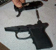
To remove the hammer (for the P-11 only, the P-32 does not require this), you must first remove the Hammer Spring Catch (Part 279) from the hammer spring (Part 275). Do this by pushing the hammer spring up and out of the Hammer Spring Catch and then sliding out the Hammer spring Pin (Part 273). Then you can pull the hammer spring out of the hammer spring catch. Now push the Hammer Axis pin (Part 278) from the right out the left side. This should not require force and often falls out if the frame is held with the left side down and tapped.

click to enlarge

click to enlarge

click to enlarge


For the P-11, simply pull the hammer up and out with the hammer spring. For the P-32 just slide the hammer down

click to enlarge

click to enlarge

click to enlarge


Removing the trigger and trigger axis

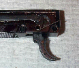
(For the P-11 and P-40 only, not the P-32, the P-32 has no access hole in the frame to push the trigger pin out, so the trigger must be broken to remove it.) To remove the trigger from the frame you must first remove the trigger pin (part 253) by pushing it out through the bottom. There is a small hole in the frame that will line up with the pin when the trigger is in the forward position. Insert a small enough punch into the hole in the frame and tap out the pin. Then the Trigger Axis (part 254) can be pushed out to the right.

click to enlarge

click to enlarge


Removing the firing pin

(Pictured for the P-11 and P-40, but the same for the P-32)
The firing pin (part 170) is under tension at all times by the Firing pin Spring (part 172) and is held in place by the firing pin screw (part 174) which dips down into the channel cut into the firing pin. Insert an allen wrench into the firing pin screw and break it loose (as it should have lock tite on it to keep it from moving) but don't take it out yet. Now that you have the screw broken loose, get something else to put pressure on the firing pin from the rear, I use another allen wrench. Push the firing pin forward a little, then remove the firing pin set screw. When you get the set screw most of the way out, you can slowly release the pressure on the firing pin, and it will come out. Be careful not to let the firing pin slip as it can fly out and hit you or at the very least, get lost.


Putting the firing pin back in

Slide the firing pin spring over the end of the firing pin and put it into the slide from the rear with the slot cut in the firing pin up. Apply a drop or 2 of medium lock tite to the exposed threads on the firing pin set screw. Now push the firing pin into the hole, and tighten the set screw until it lightly bottoms out against the bottom of the slot in the firing pin. Then back the set screw out 1/2 a turn. Slowly release the pressure on the firing pin and it should stay in the slide and move smoothly forward and back


Extractor


This is only needed if you wish to change or modify the extractor, or occasionally clean this area out.

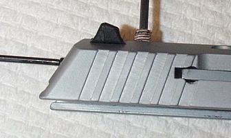
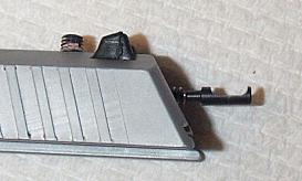
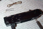
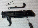
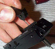
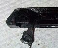
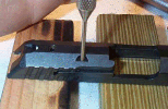
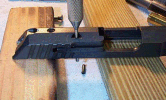
After you have the slide off get a punch (or something the right size) and and tap out the extractor roll pin out of the bottom with the slide rested on something giving the roll pin somewhere to go (2 pieces of wood, or a piece of wood with a hole in it).


click to enlarge

click to enlarge
As you tap out the roll pin the punch will hold the extractor in place.
 

click to enlarge
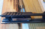
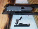
Hold in the rear of the extractor as you pull out the punch, the extractor will be under tension by the extractor spring. As you let the tension off the extractor, it and the spring should fall out of the right side.


click to enlarge
To reinstall, insert the spring into the round portion in the extractor slot in the slide, then put in the extractor. Push in on the extractor while looking down on the slide to line up the hole in the extractor with the one in the slide, and insert the punch from the bottom towards the top. Then start the roll pin in through the top and as you do, you will push out the punch through the bottom. Make sure the roll pin is not sticking out to far of the bottom of the slide, if it is, it can hit the frame and cause binding.


Assembly


To put the trigger assembly back together (for the P-11 or P-32), first push the trigger up into the frame. Then slide in trigger axis (part 254) from the right side of the frame. Now put the trigger pin (part 254) in the bottom of the trigger. Start to push it up into the trigger. Now you will probably have to turn the trigger axis a little, and maybe move the trigger back and forth a little until the holes line up so the pin can go through the first part of the trigger axis. At this point, only push the pin through the trigger axis enough to keep the holes lined up. Now insert the loop end of the trigger spring (part 256) into the trigger axis, and rotate the "leg" of the spring so it points forward (like in the first pic). Then push the pin the rest of the way into the bottom of the trigger (the pin should go through the "loop" at the end of the trigger spring that goes into the trigger axis).

click to enlarge

click to enlarge


To reassemble, (for the P-11) slide the hammer spring down through the frame and position the hammer so the flat side is to the left. For the P-32 the flat side of the hammer goes forward and the hammer goes in up from the bottom of the frame, not down from the top. Then push in the hammer axis pin (part 276) from the left side. On the P-32 the rounded end of the Hammer Axis goes to the right side. Now slide the hammer spring catch over the end of the hammer spring and rotate it so that the curved part is to the rear. Insert the hammer spring catch pin and set it into the hammer spring catch by pulling the hammer spring catch away from the frame.

click to enlarge

click to enlarge


Now lay the frame on it's right side (so you are looking at the left side) and put the slide stop back in, it will go in without force, but you may have to do some twisting. Flip the frame over so you are looking at the right side. Lay the transfer bar on the frame. Now pull the trigger spring down (counter clockwise) and set it in the groove of the transfer bar. Pick up the frame holding the transfer bar against it and keeping the slide stop against the frame and begin inserting the hammer spring into the mag well and start the frame going into the grip. Push it into the grip far enough so that the grip will hold the transfer bar in the frame. Now look at it from the left side and put the slide stop/assembly pin spring in place (part 284) making sure it is against the slide stop and totally in the groove machined in the frame with the slightly shorter side down (if one side is shorter). Now always keeping your finger over this spring, holding it against the frame, push the frame the rest of the way into the grip.

click to enlarge

click to enlarge

click to enlarge

click to enlarge


If you are assembling a P-32 you will notice that the rear of the frame will not go all the way into the grip. This is because of the hammer block. The P-11 does not have this. You will want to push the hammer to the forward position, and lift the rear of the frame slightly off the grip and put a small object in there to push the hammer block forward. I use a hex driver (same one I use to push out frame pins). Then with the hammer forward and forward pressure on the hammer block with your tool, push the frame down and sandwitch your tool with the frame and the grip. Now slide your tool out and the frame should seat all the way in the grip.

click to enlarge

click to enlarge

click to enlarge


Now start the frame pins in the grip/frame from the same side you pushed them out from and in the same direction you pushed them out. Also push on the same side of the frame pin to put it in that you used to push it out and push the pin flush with the grip.

Use the same flat blade screwdriver to "hook" the hammer spring catch on the bottom of the grip.

click to enlarge

click to enlarge

click to enlarge

click to enlarge

click to enlarge

click to enlarge

click to enlarge


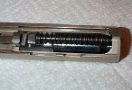
Now insert the barrel into the slide, put the recoil springs on the guide rod, and insert the guide rod into the slide, making the head catch on the cutout in the barrel in front of the lug area.

click to enlarge


If working on a P-3AT insure the ejector is in the aluminum frame. (it just sets in there, nothing holds it in but the slide)

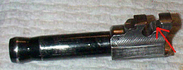
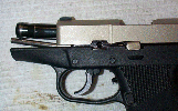
Now insert an empty mag into the grip (or push up on the slide stop when you pull the slide back). The slide does not need to be locked back to insert the assembly pin it only has to be pushed back slighly, but it is usually easier to lock it back on the P-11 and the P-32. Slide on the slide assembly (Slide, barrel, recoil spring and guide rod) and pull it all the way back (for the P-3AT and P-32 the hammer needs to be in the half cock position for the slide to go on). It should lock back (for the P-32 and P-11). The barrel should fall forward, but may not go all the way forward, or may go a little too far forward. You will probably have to move the barrel a little forward and/or back to get the assembly pin hole and the lug area (red arrow in the first pic below) in the barrel lined up. Once you have the barrel fully forward (as in the second picture below), move it back and forth a bit and you will find a round slot for the assembly pin to be inserted into. Make sure you have the top of the pin up (slot for the spring and groove for removal up), and make sure the slot is fully open and NOT BLOCKED AT ALL by the barrel. Once all of these things are done, the pin will slide into the slot and when you push it home, it will snap into place. Then you release the slide stop and work the slide a few times to check the action, as directed in the all too brief assembly instructions in your KelTec instruction manual.

click to enlarge

click to enlarge


If at this point you find your slide will not go all the way back, nor will it slide forward, your guide rod has probably slipped back past the cutout in the frame it should rest in.
If so then look here.

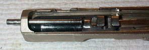
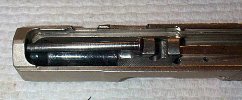
On my p-11 I found that I could not get my barrel to go forward enough to line up with the assembly pin hole sometimes. This was because the top of the guide rod was hitting the first ledge on the barrel and not staying in the cup that is there to hold it (first picture). It should rest in the cup like in the second picture. The recoil spring was pointing down, normaly it will point up. To get the barrel forward I had to push up on the tip of the guide rod which forced the inside head down off the ledge on the barrel into the cup that holds it. I rounded this first lip on my p-11 barrel so the head of the guide rod will slip off of it and fall into the cup, this was not necessary on my p-32

click to enlarge

click to enlarge

click to enlarge

click to enlarge

click to enlarge