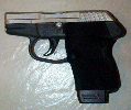
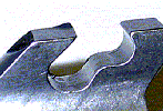
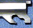
Assembly Pin ModificationMake sure you have the latest designpins posted by marlin336 and ppmd on the KTOG board.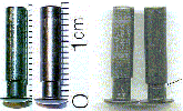 click to enlarge The pin on the left was the first design of the P-3AT pins with the beveled shoulder, and some had a tendancy to pop out. Then KT decided to deepen the groove and make it more of a sharp shoulder, but put it in the wrong place!! (third pin from the left) This allowed the pin to be pulled out from the frame a litte before the shoulder even hit the spring holding the pin in, and also caused pins to walk. Then lastly the pin on the right with the groove all the way around (same as the second pin from the left) is the most recent KT designed P-3AT pin, with the most agressive grove to retain the pin, and in the correct location. Here are 2 more pics of the newest pin with the groove:
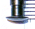
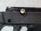
The pin can pull out just a little bit, but the head of the pin should not protrude further out than the lip around it in the grip before it engages the spring. This is the pin pushed all the way in, and pulled out until it engages the spring:
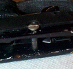
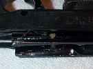
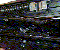
Make sure the spring engages the pin correctly
If your spring does not protrude as much as mine in these pics the next thing to look at is if the curved end of the slot cut into the frame to hold the spring in place is keeping the spring from resting flat against the top edge like it is in these pics 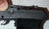
click to enlarge If the tip of the spring is hitting the curved edge of the groove in the frame before the entire leg of the spring can rest on the top edge of the grove (the way it should be as shown in the above pics) then you can trim the top leg of the spring, or just slightly bend the tip of it down. 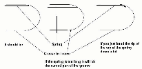
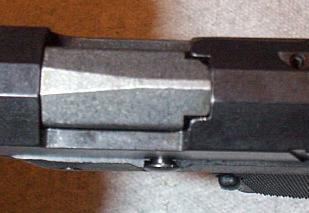
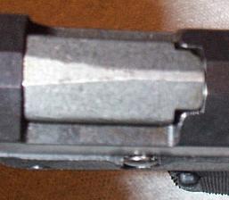
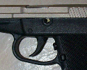
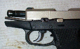
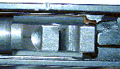
click to enlarge If the top leg of your assembly pin spring is resting flat against the top portion of the groove for it in the frame and you still do not have a similar amount of it protruding into the assembly pin area as mine, then the groove has been milled into your frame incorrectly (too far down, or to narrow), and I would call KT and try to get another frame all together. If you do have a similar amount of spring showing in the assembly pin area, and want to further the retention of the pin you can deepen the groove in the pin, which will allow the spring to rest further in the pin and more positively retain it. Before modifying your assembly pin you may want to order a spare from KT, this way if you don't like the mod or mess it up, you have an original part to replace it with, plus they are cheap... I have heard a couple of people have had a problem with the assembly pin backing out, and though I never had that problem, I never wanted to either. In the P-11 this will cause the slide to lock back if the pin pops out a little while firing. So I depend the groove in the assembly pin that the spring fits into to hold the pin in more securely. This allows the spring (part 284 here and here) to engage the assembly pin more and make it less likely to be able to work its way out. Make sure the pin is not to short or to longTo check the length of the pin in your pistol, remove the frame pins and pull the frame out of the grip then remove the trigger bar(for instructions on that look here). Now put the frame almost all the way back in the grip, just far enough that the head of the pin will hit the grip (to keep it from being pushed in to far) but not completely pushed into the frame so you can see the end of the pin on the right side, as shown in these three pics:
Make sure your frame is not damaged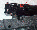
click to enlarge Here are some excellent pictures of barrel and frame dammage on a P-3AT from pin walk out, posted by ppmd on KTOG.
Make sure the left side of your grip does not bow outAs you are looking down at the pistol, the left side of the grip (right around the assembly pin) should be flush with the frame and not bow out at all. The side of the grip is all that is holding in the assembly pin spring, so if it bows out the spring will pop out and allow the assembly pin to work its way out. Even if it is flush with the frame, sometimes a slight inward bow is desirable to help keep a stubborn assembly pin spring in place. To achieve this, simply remove the frame from the grip, then heat the left side of the grip (around the assembly pin, a hair dryer works well) and while it is warm push in on that side and hold it in until it cools. It will then stay that way, and apply more pressure on the assembly pin spring to hold it in.For the P-11:(I did not think of this until later, but a hack saw blade, cutting in the same place, would probably be easier, and give you a straighter cut) 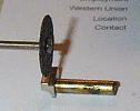
click to enlarge If you do this you may not be able to just pull the pin out, because the spring is too far into the pin. So you have to push the spring back with a small screwdriver then pull the pin out. To me this is a small price to pay for knowing the pin will not back out on me. 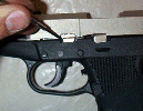
click to enlarge For the P-32 or the P-3AT:
click to enlarge only deepen the dip in the pin in one spot, this will be where the spring rests in the pin. Then I cut a groove in the end like this: 
click to enlarge so now to remove the pin I use a straight screw driver (or the rim of a case) and turn the pin 180 degrees and pull it out like normal. When you put it back in, make sure you put the groove facing down towards the spring, or you can just turn it until you feel it "click" into place with the spring. Here you can see the spring that holds in the assembly pin on the p-32, and the pin installed on mine:
I still don't know why KT will not make P-32 and P-3AT pins like this from the factory,the only thing I can think of, is that I suspect they don't want to take the groove as far as I did (requiring a turn to get the pin out) because it would be very obvious there was a change, and it would need a change in the assembly instructions, and manuals. Not to mention that if someone tries to pull the pin out without turning it, he will likely break the grip, bend the assembly pin spring, or at least dislodge the spring requiring the frame to be pulled to put it back.If I were doing this mod in production I think I would shave off the top part of the head of the pin. So it would look like a D turned 90 degrees clockwise looking at the pistol with the pin installed from the left side. This would give a visual indicator of which way the groove was, and make it so that you could not try to pull it out without first turning it. One more thing to keep in mindis that now you have cut through the protective coating in the groove. That coating (blueing or what ever) was there to keep it from rusting. Now you should at very least put some cold-blue on it to keep it from rusting. I performed all my mods to mine first then sent it out to be plated by Jack.If you are worried about weakening the assembly pin:Actually the part I made weaker (where the groove is) could actually be cut completely off and the pin would still function 100%... The only danger in making the groove too deep is that the spring that holds it in place, pushes against the assembly pin on one side and against the slide lock on the other side. I would guess that if you went nuts on the groove and made it really deep, it could take some pressure off the slide lock and not hold it down with the intended force witch could cause it to jump up when firing and lock the slide back prematurely. But that is very hypothetical (as deepening the groove a little, like 1/8", does not affect the spring tension that much). I have never had this happen, and don't worry about it the slightest bit. Think about the part of the pin that is doing the work, it is the part inside the frame and goes out to the edges of the frame. The part I cut the groove in is at the very outside edge of the frame. If you were to cut it off at the groove, it would look a bit like the pin holding in the hammer wouldn't it? The only reason the assembly pin is longer than the pin holding in the hammer, is that you need to be able to pull it out to disassemble it. Maybe my crude drawing will clear up my point a bit: 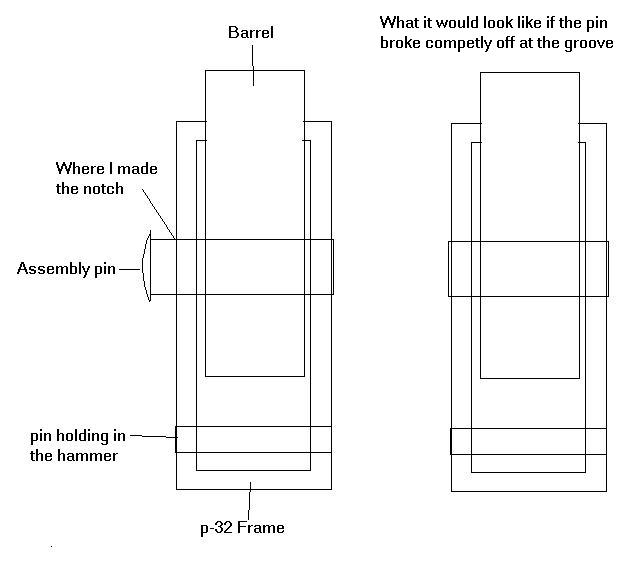
This applies to both the p-11 and p-32 the same... |
 click to enlarge
 click to enlarge
 click to enlarge
 click to enlarge
 click to enlarge
 click to enlarge
 click to enlarge
 click to enlarge
 click to enlarge
 click to enlarge