Ruger MKII Internal Disassembly
and Reassembly Instructions
Back to Ruger MKII Stuff
All part numbers refferenced can be found here, and
all up, down, left and right directions are assuming you are holding the
pistol with a firing grip and pointing it away from you (duh).
|
First insure the gun is unloaded and remove the receiver (instructions for that here). Then remove
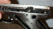
the grips and magazine. Your trigger hammer frame assembly should look like this (with the grips off that is):
|
|
|
|
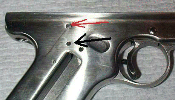
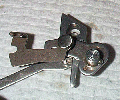
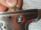
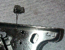
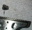
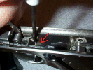
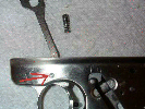
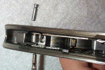
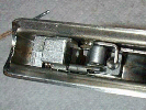
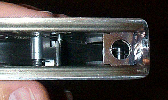
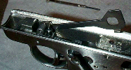
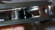
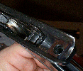
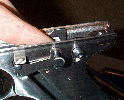
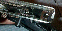
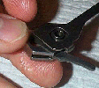
You now need to tap out the hammer pivot pin(A02605) (also holds in the disconnector, safety, and bolt stop) from the right side of the grip, pressing it
out to the left with a punch. (press on the pin with the Red arrow). This
should not take much force, maybe one light tap with a very small hammer to get
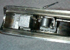
it started, then it should pull right out. The third pic shows the pin
starting to come out.
|
|
|
|
When removing the pin try to make a note of how the pieces are oriented in the
frame. If you pull the pin out and hold it upside down, they will all fall
out. Just to show the order of the parts, if pressing the pin in from the left to the right, it passes through the
bolt stop, then the first side of the frame, then the safety, then the hammer,
then the disconnector and finally the second side of the frame. If the pieces
came out and your not sure how, don't worry I will explain more later during
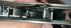
reassembly. Here is a pic of the items the pin passes through and their
orientation without the grip, and the second pic is how the pin would go
through the items from left to right (on the gun) shown from top to bottom (in
the pic)
|
|
|
|
Now that you have the hammer pivot pin out, the hammer(A01800), safety(AN-53) and bolt stop(A04700)
can be removed (or will have fallen out), and the disconnector can be pivoted up (you may have to push
the sear forward to allow the disconnector to pivot up, first pic shows the screwdriver pushing the sear forward). You may have to twist
the safety clockwise (as looking at the left side of the gun) to remove it from
the frame, be careful not to loose the ball and spring that give you the
positive click of the safe and fire positions (red arrow) that are in a hole in
the rear of the safety lever.
|
|
|
|
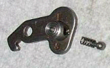
Now pivot the disconnector(KA011) up/forward so that the spring(A20400) and
plunger(A02508) in the top of
the trigger may be removed(red arrow) and set them aside (I remove them
here so they don't fall out later).
|
|
|
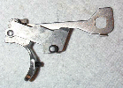
Now you may remove the trigger and or the sear. I'll start with the sear.
|
Push out the sear pin(A02601) from the right side (pushing it out the left side, black arrow in pic). As
you do this try to take note as to the orientation of the sear(A01901), and sear
spring(A03100). Lift out the sear and sear spring. You can leave the Sear Spring Retaining Pin (A02603) where it is.
|
|
|
|
To remove the trigger pivot pin(A03400) you must push down the retaining spring(KA04200)
on the right side inside the frame, then
push the pin out from the left to the right side (opposite side as the other
pins). The spring rests in a slot in the pin and must be pressed down for the
pin to be removed. (Spring, red arrow, being pressed down with screwdriver in pic)
|
|
|
|
With this pin out you may remove the Bolt Stop (AN-37), the Bolt Stop Spring (A04600; blow up dwg.) and Plunger (A04300; blow up), the Disconnector (KA011) and the Trigger Assembly (A01200, A20400, A02508) can be removed (in that order). Note: the Bolt Stop Spring and plunger are almost identical to the extractor spring and plunger so to avoid a mix-up, save the replacement of the extractor (instructions for that here) until after you get the trigger back together.
|
|
|
Reassembly:
|
First put the forward part of the disconnector into the top hole in the trigger.
Then slide the triger into the frame (with the disconnector still attached to it).
Now slide the Bolt Stop Spring onto the Blot stop plunger, and both of them
(spring first) into the hole for them in the frame (right above the trigger)
with the cut out in the pluger to the outside of the frame (like in the pic).
|
|
|
|
Now use a screwdriver to push down the retaining spring and begin to insert
the trigger pivot pin from the right side and partialy through the trigger.
Insert the Bolt stop and push it forward to line up the hole in that with the
hole in the trigger and the hole in the frame. Then push the trigger pivot pin
the rest of the way through. Second pic shows how the disconnector, trigger,
and bolt stop fit together outside of the frame.
|
|
|
|
Drop in the sear as shown and line it up with the hole in the frame and start
the pin from the right of the frame going partialy through the sear. This will
allow you to get the spring lined up on the left side of the sear. When the
sear is installed it should look like the second pic. The spring should be
long end down and should catch on (and be infront of) the Sear spring Stop
pin(A02603) as in the last 2 pics. The sear spring should be putting tension
on the sear so that the top of the sear, wants to rotate towards the rear and
will have to be held forward when you put in the hammer. The short end rests
on the sear, and is toward the center of the pistol.
|
|
|
|
Now lift the desconector up and put in the Trigger spring(A20400) and Trigger
Spring Plunger(A02508), then swing the disconnector back down. Push the sear
forward and the disconnector down then release the sear and it will hold the
disconnector down and the sear forward.
|
|
|
|
Here is a look again at how the parts will fit together on the hammer axis pin:
|
|
|
|
Lay the pistol on it's right side. Now lay the bolt stop thumb lever on the
frame inserting the nub of the bolt stop lever into the slot on the thumb lever
(as shown in pic). Now insert the safety in the frame as shown in the first pic (be careful not
to lose the little ball and spring). Now rotate the front of the safety lever
down so that the hole in the front of the lever lines up with the hole in the
frame and the hole on the bolt stop thumb lever. When you do this you will
push the sear forward (with the safety lever) and the disconnector will
probably pop up, let it do so, but keep the safety lever, frame and thumb lever
lined up. Now begin to insert the trigger axis pin so that it is through the
thumb lever, frame and safety, but not further. The pin (only partially
inserted) will now hold them in place.
|
|
|
|
Now with the bushing inserted on the right side of the hammer put the bushing in
the square opening in the disconector (the hammer strut is to the rear of the
hammer). Now drop down the disconnecor and hammer together into the frame, and
push the hammer axis pin the rest of the way thorough the frame.
|
|
|
Now put the grips back on, and reassemble as
usual.
|
